How to Read Instrument Approach Procedure (IAP)

Instrument Approach Procedure (IAP) are a predetermined set of instructions for pilots to transition from an approach to landing phase. Each runway equipped with different navigational guidance, such as ILS, RNAV, VOR, etc., will contain an unique IAP chart to land at that airport.
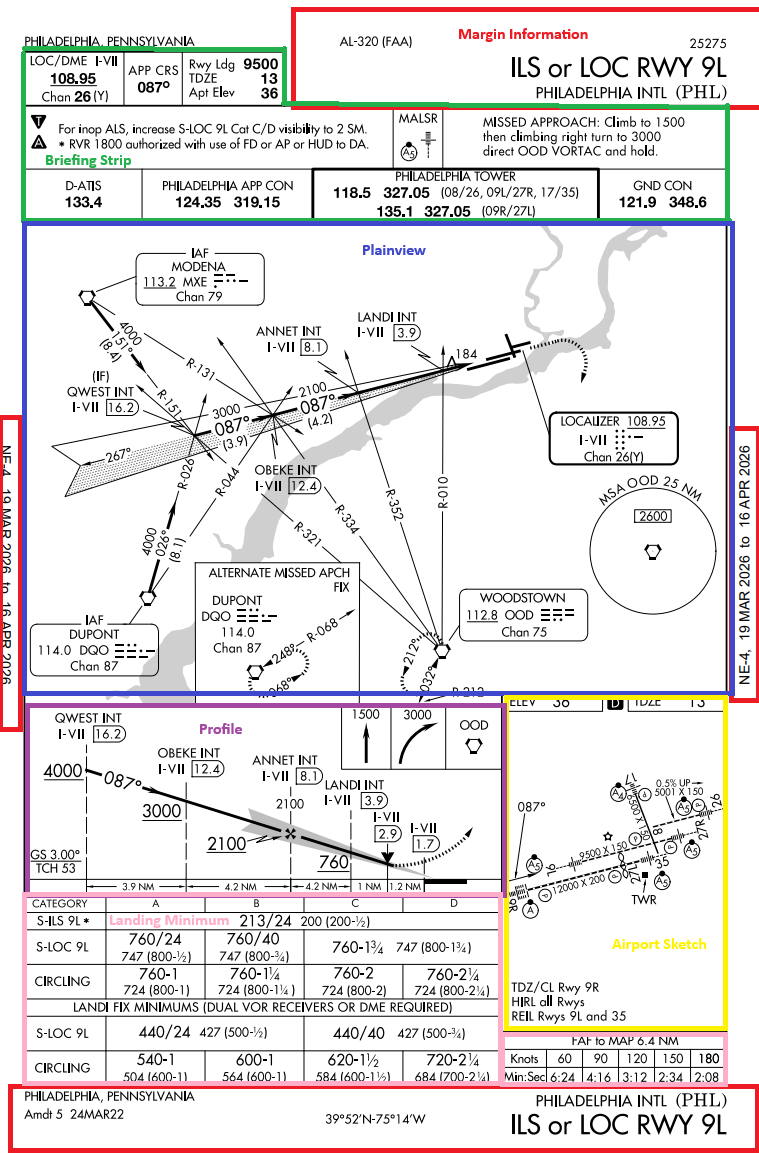
Margin Information
Margin Information provide information around the top, side, and bottom of the IAP.
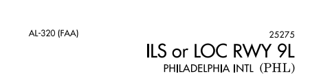
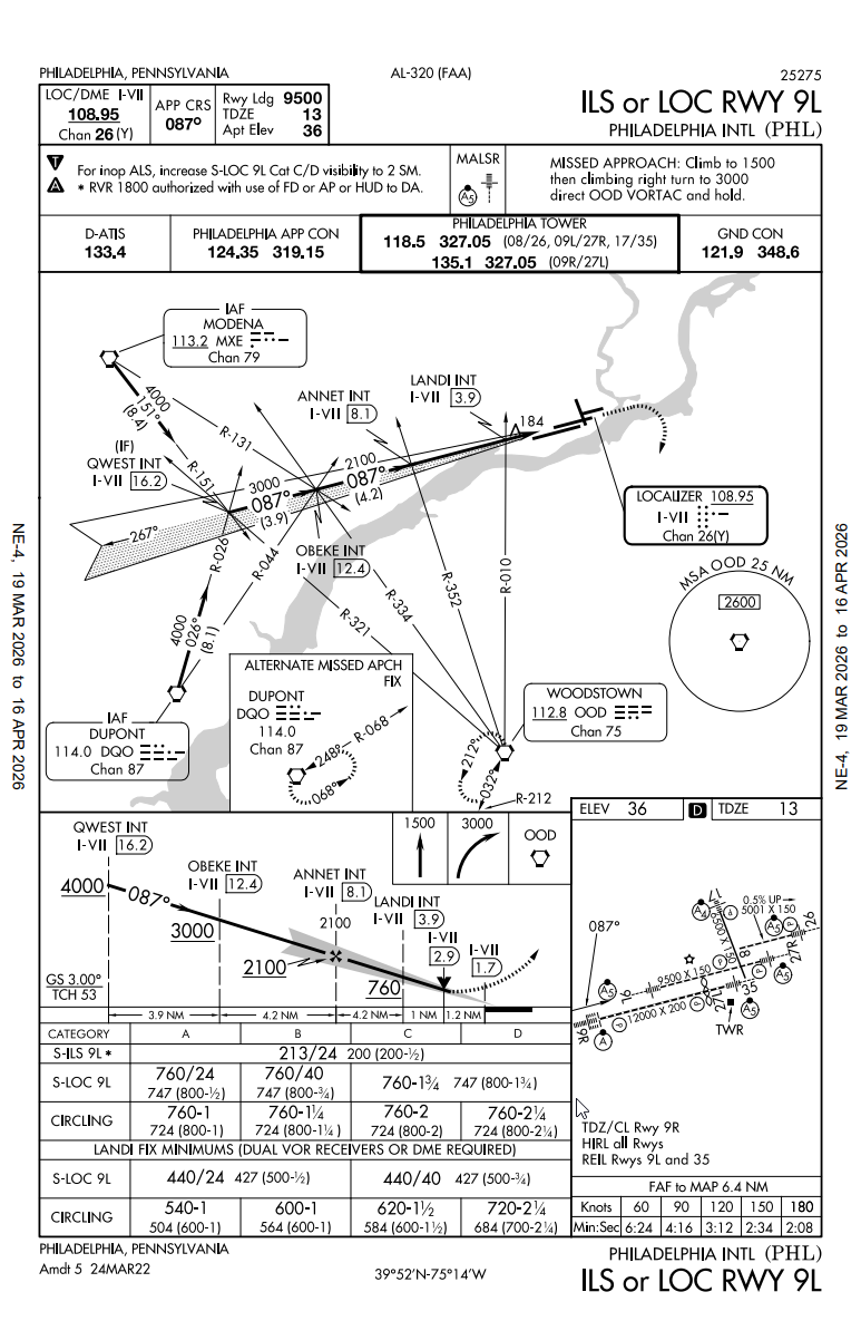
The top of the page will say what type of approach and airport the IAP is used for. This is the ILS or Localizer for Runway 9 left at Philadelphia International Airport (PHL).
The side of the IAP plate will say the dates the IAP is valid for.

The bottom of the IAP shows more information such as the coordinates and the amendment number with the date issued.
Briefing Strip
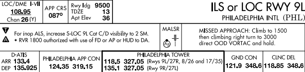
At the top left of every IAP, the section called the "Briefing Strip" consists of three area called:
- Top Briefing Strip
- Middle Briefing Strip
- Communications Briefing Strip
Top Briefing Strip
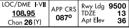
Box 1 will contain the primary navigation type used for the approach. Since this is an ILS or Localizer approach, the primary navigation type is the Localizer and DME.
Box 2 is the final approach course heading (087)
Box 3 contains the longest runway (9500), the Touchdown Zone elevation (13), and Airport Elevation (36).
Middle Briefing Strip

Box 1 is the note section. Any notes due to inoperative lights, radar, etc will be noted here, including their increased or decreased restriction to landing minimums. The symbols on the left of Box 1 can show additional information that a pilot may need.
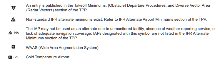
Box 2 is the Approaching Lighting System. It will show the light name of the lighting system and the symbol.
Box 3 is the missed approach. It will explain in textual form on how to do a missed approach procedure.
Bottom Briefing Strip

Box 1 is the ATIS, D-ATIS, AFIS (AK Only), ASOS/AWOS frequencies
Box 2 is the approach control name and frequencies
Box 3 is the tower control's frequencies for every runway. We will use 118.5 for Runway 9 left
Box 4 is the ground controller frequency
There can be additional boxes such as the Clearance Delivery, UNICOM, Controller Pilot Data Link Communication, or Ground Communication Outlet frequencies.
Plainview
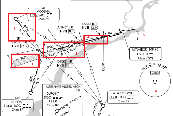
- Initial Approach, the beginning segment of the approach.
- Initial Approach Fix - nearby navaids or waypoints that the aircraft first fly to transition into the approach
- Intermediate Approach - the segment between the initial approach point and the final approach fix.
- Final Approach Course - the final course of the approach which will include the final approach fix.
- Missed Approach - the missed approach track and the direction to turn
- Minimum Safe Area - guarantee 1000 ft obstacle clearance at that certain altitude, 25 NM radius from a navaid or airport. (At 2600 ft at the OOD VORTAC, you will be guaranteed 25 NM of 1000 ft obstacle clearance)
Profile
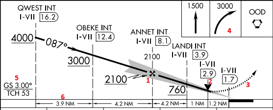
- Final Approach Fix - Maltese Cross for non-precision approach, lightning bolt for precision approach.
- Visual Descent Point - for nonprecision approach, if you are able to see the runway, you can now proceed to the MDA (minimum descent altitude)
- Missed Approach
- Missed Approach Illustration
- Glidepath degree
- Distance between each segment
Landing Minimums
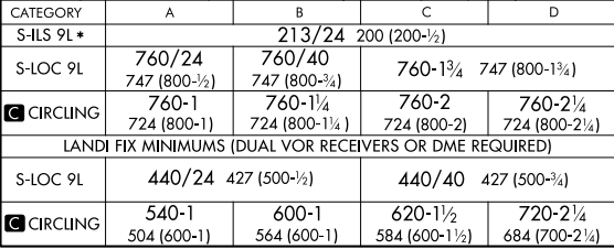
Category is your aircraft's approach category.
You will read the type of approach you doing and line up with the vertical table of your cateogry. For example for S-ILS 9L:
- The landing minimum is for ALL category aircraft
- 213/24 = 213 Decision Altitude, 2400 ft Runway Visual Range
- 200(200-1/2) = 200 Height Above Threshold (HAT), (200 Decision Height - 1/2 sm visibility)
Generally the precision approach will have the lowest landing minimums.
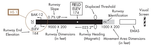
Airport Sketch
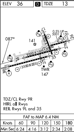
The airport sketch will contain information such as:
- The elevation and touchdown-zone elevation (TDZE)
- Lighting system for each runway
- Length and width of the runway
- Tower location
- Up slope and down slope percentage
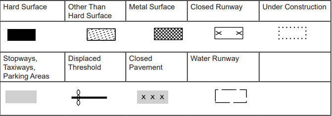
Below are two legends that will help read the airport sketch and runways:
You should also read:
How to Read a SID Chart
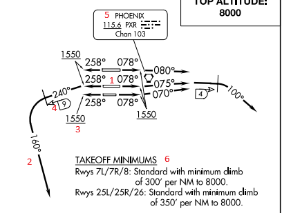
A SID (Standard Instrument Departure) is a departure procedure used by the pilot and controller to provide obstacle clearance and provide an uniform departure transition from terminal to the departure control. A SID will include climb, heading, and transitions to a fix in order to…
Continue reading...
How to Read All METAR Remarks
Remarks are at the end of a METAR that will explain further details about the current weather at the designated location. They can add further details about tornadoes, winds, visibility, temperature, pressure, etc. Read and understand about METARs before diving into the Remarks. Below is…
Continue reading...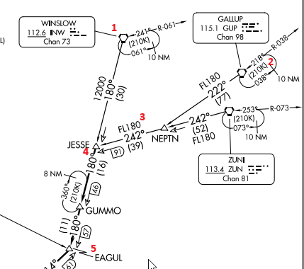
How to Read A STAR Chart
A Star (Standard Terminal Arrival Procedure) is a published instrument approach procedure that are used by pilots and ATC to transition from the en route phase to the approach phase of flight. It streamlines traffic into the airport, like "gates" into a baseball stadium. There…
Continue reading...